ASTM F835/F835M Alloy Steel Screws Specification
Quenched & Tempered Alloy Steel Hexagon Socket Button & Flat CounterSunk Head Cap Screws
ASTM F835/F835M Socket Button and Flat Countersunk Head Cap Screws
ASTM F835 specification covers the requirements for quenched and tempered alloy steel hexagon socket button (SBHCS) #0 through 5/8 inch thread sizes and flat countersunk (SFHCS) #0 through 1 1/2 thread sizes head cap screws having material properties for high-strength requirements. ASTM F835 Fasteners meeting this specification are intended for shear-type applications and have tensile requirements ranging from 122 to 150 ksi.The screws shall be fabricated from alloy steel made to fine grain practice. In the event of controversy over grain size, referee tests on finished screws conducted in accordance with Test Methods E112 shall prevail. ASTM F835 Screws shall be hot or cold upset or extruded, or both. Unless otherwise specified, threads shall be rolled for diam eters through 5/8 Inch and for screw lengths through 4 Inch For diameters and lengths other than this, threads may be rolled, cut or ground.
ASTM F835/F835M Chemical Requirements
| Element | Heat Analysis | Product Analysis |
|---|---|---|
| C | 0.30 to 0.48 | 0.28 to 0.50 |
| P, max | 0.035 | 0.040 |
| S, max | 0.040 | 0.045 |
ASTM F835/F835M Mechanical Requirements
| Type | Mechanical Requirements | Nominal Thread Size, in. | |
|---|---|---|---|
| 0.500 andsmaller | Over 0.500 | ||
| Full-size Screws | Tensile, min, ksi | 144 | 136 |
| Machined Test Specimen | Yield strength at 0.2 % offset, min, ksi | A | 153 |
| Tensile strength, min, ksi | A | 170 | |
| Elongation in 4 D , min, % | A | 8 | |
| Reduction of area, min, % | A | 35 | |
| Product Hardness | Rockwell C | 39-44 | 37-44 |
| Vickers DPH | 382-434 | 363-434 | |
|
|||
ASTM F835/F835M Minimum Ultimate Tensile Loads
| Thread Size | Stress Area,B in.2 | Button and Countersunk Heads, Tensile Load, min lbA |
|||
|---|---|---|---|---|---|
| Coarse | Fine | Coarse | Fine | Coarse Thread Series | Fine Thread Series |
| . . . | 0.060-80 | . . . | 0.00180 | ... | 260 |
| 0.073-64 | 0.073-72 | 0.00263 | 0.00278 | 380 | 400 |
| 0.086-56 | 0.086-64 | 0.00370 | 0.00394 | 530 | 570 |
| 0.099-48 | 0.099-56 | 0.00487 | 0.00523 | 700 | 750 |
| 0.112-40 | 0.112-48 | 0.00604 | 0.00661 | 870 | 950 |
| 0.125-40 | 0.125-44 | 0.00796 | 0.00830 | 1150 | 1200 |
| 0.138-32 | 0.138-40 | 0.00909 | 0.01015 | 1310 | 1460 |
| 0.164-32 | 0.164-36 | 0.0140 | 0.01474 | 2020 | 2120 |
| 0.190-24 | 0.190-32 | 0.0175 | 0.0200 | 2520 | 2900 |
| 0.250-20 | 0.250-28 | 0.0318 | 0.0364 | 4580 | 5240 |
| 0.3125-18 | 0.3125-24 | 0.0524 | 0.0580 | 7550 | 8350 |
| 0.375-16 | 0.375-24 | 0.0775 | 0.0878 | 11 200 | 12600 |
| 0.4375-14 | 0.4375-20 | 0.1063 | 0.1187 | 15 300 | 17100 |
| 0.500-13 | 0.500-20 | 0.1419 | 0.1599 | 20 400 | 23000 |
| 0.625-11 | 0.625-18 | 0.226 | 0.256 | 30 700 | 34800 |
| 0.750-10 | 0.750-16 | 0.334 | 0.373 | 45 400 | 50700 |
| 0.875-9 | 0.875-14 | 0.462 | 0.509 | 62 800 | 69200 |
| 1.000-8 | 1.000-12 | 0.606 | 0.663 | 82 400 | 90400 |
| . . . | 1.00-14 UNSC | . . . | 0.680 | . . . | 92500 |
| 1.125-7 | 1.125-12 | 0.763 | 0.858 | 104 000 | 116400 |
| 1.250-7 | 1.250-12 | 0.969 | 1.073 | 132 000 | 146000 |
| 1.375-6 | 1.375-12 | 1.155 | 1.315 | 157 000 | 179000 |
| 1.500-6 | 1.500-12 | 1.405 | 1.581 | 191 000 | 215000 |
|
|||||
ASTM F835/F835M Decarburization Limits
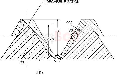
| Threads/in. | Thread Height, hs | 0.75 hs from Root to Crest, min | 0.1 hs at Root, max |
|---|---|---|---|
| 48 | 0.013 | 0.010 | 0.001 |
| 44 | 0.014 | 0.011 | 0.001 |
| 40 | 0.015 | 0.011 | 0.002 |
| 36 | 0.017 | 0.013 | 0.002 |
| 32 | 0.019 | 0.014 | 0.002 |
| 28 | 0.022 | 0.017 | 0.002 |
| 24 | 0.026 | 0.020 | 0.003 |
| 20 | 0.031 | 0.023 | 0.003 |
| 18 | 0.034 | 0.026 | 0.003 |
| 16 | 0.038 | 0.029 | 0.004 |
| 14 | 0.044 | 0.033 | 0.004 |
| 13 | 0.047 | 0.035 | 0.005 |
| 12 | 0.051 | 0.038 | 0.005 |
| 11 | 0.056 | 0.042 | 0.006 |
| 10 | 0.061 | 0.046 | 0.006 |
| 9 | 0.068 | 0.051 | 0.007 |
| 8 | 0.077 | 0.058 | 0.008 |
| 7 | 0.088 | 0.066 | 0.009 |
| 6 | 0.102 | 0.077 | 0.010 |
ASTM F835/F835M Bolting Surface Treatment Specifications
ASTM F835/F835M Bolting Components Marking
Product Shall be Marked with our manufacturing trade mark "TorqBolt" or "TB" along with the
designated Grade.
Grade and manufacturer’s identification symbols shall be applied to one end of studs and to the heads of
bolts and screws of all sizes. (If the available area is inadequate, the grade symbol may be marked on
one end and the manufacturer’s identification symbol marked on the other end.) For bolts and screws
smaller than 1⁄4 in. [6 mm] in diameter and studs smaller than 3⁄8 in. [10 mm] in diameter and for 1⁄4
in. [6 mm] in diameter studs requiring more than a total of three symbols, the marking shall be a matter
of agreement between the purchaser and the manufacturer.
ASME Dimensional Standards
B18.3
Hexagon Socket Head Cap Screws
B18.3
Hexagon Socket Head Shoulder Screws
B18.3
Hexagon Socket Flat Countersunk Head Cap Screws
B18.3
Spline Socket Head Cap Screws
B18.3
Hexagon Socket And Spline Socket Button Head Cap Screws
B18.3
Hexagon And Spline Socket Set Screws
B18.3
Hexagon And Spline Socket Set Screw Optional Cup Points
ISO 4762 Socket
Head Cap Screws
ASTM F835/F835M Bolting Certifications
- EN 10204 3.1
- EN 10204 3.2
- PED 2014/68/EC
- MERKBLATT AD 2000 W2/W7/W10
- API 20 E BSL 1/ BSL 2
- NACE MR 0175
- NACE MR 0103
ASTM F835/F835M Testing Standards
A751 Test Methods, Practices, and Terminology for Chemical Analysis of Steel
Products
E112 Test Methods for Determining Average Grain Size
F788 Specification for Surface Discontinuities of Bolts, Screws, and Studs, Inch
and Metric Series
E18 Test Methods for Rockwell Hardness of Metallic Materials
E384 Test Method for Microindentation Hardness of Materials
ASME Threading Specifications
ASME B1.1 Unified Inch Screw Threads (UN and UNR Thread Form)
ASME B1.3 Screw Thread Gaging System for Dimensional Acceptability - Inch Screw
Threads (IN, UNR, and UNJ)
ASME B1.13M Metric Screw
Threads - M Profile
ASME B1.21M Metric Screw Threads - MJ Profile
ASME B1.2 Gauges & gauging for Unified Screw Threads(Imperial)