ASTM F3111 Structural Bolting Specification
Heavy Hex Structural Bolt/Nut/Washer Assemblies, Alloy Steel, Heat Treated, 200 ksi Minimum Tensile Strength
ASTM F3111 Chemical Requirements
| Element | C | Mn | P | S | Si | Cr | Mo | V | ||
|---|---|---|---|---|---|---|---|---|---|---|
| Bolts | Heat Analysis, % | min | 0.38 | 0.4 | . . . | . . . | . . . | 1.2 | 0.6 | 0.3 |
| max | 0.42 | 0.6 | 0.01 | 0.01 | 0.1 | 1.4 | 0.8 | 0.4 | ||
| Product Analysis, % | min | 0.36 | 0.37 | . . . | . . . | . . . | 1.15 | 0.57 | 0.27 | |
| max | 0.44 | 0.63 | 0.015 | 0.015 | 0.12 | 1.45 | 0.83 | 0.43 | ||
| Nuts | Heat Analysis, % | min | 0.3 | 0.6 | . . . | . . . | 0.15 | . . . | . . . | . . . |
| max | 0.48 | 0.9 | 0.05 | 0.05 | 0.35 | . . . | . . . | . . . | ||
| Product Analysis, % | min | 0.28 | 0.57 | . . . | . . . | 0.13 | . . . | . . . | . . . | |
| max | 0.5 | 0.93 | 0.055 | 0.055 | 0.37 | . . . | . . . | . . . | ||
| Washers | Heat Analysis, % | min | 0.42 | 0.6 | . . . | . . . | 0.15 | . . . | . . . | . . . |
| max | 0.48 | 0.9 | 0.03 | 0.03 | 0.35 | . . . | . . . | . . . | ||
| Product Analysis, % | min | 0.4 | 0.57 | . . . | . . . | 0.13 | . . . | . . . | . . . | |
| max | 0.5 | 0.93 | 0.035 | 0.035 | 0.37 | . . . | . . . | . . . | ||
ASTM F3111 Mechanical Requirements
ASTM F3111 Hardness Requirements for Bolts
| Bolt Size, in. | Bolt Length, in. | Rockwell C | |
|---|---|---|---|
| Min | Max | ||
| 1 to 1 1/4 , incl | all | 38 | 45 |
ASTM F3111 Tensile Requirements for Full Size Bolts
| Grade | Bolt Size, Threads per in. | Stress Area,A,B in.2 | Tensile Load,C lbf | Proof Load, lbf | Alternative Proof Load, lbf | |
|---|---|---|---|---|---|---|
| Min | Max | Length Measurement Method | Yield Strength Method | |||
| ASTM F3111 Grade 1 | 1 in. - 8 | 0.615 | 123 100 | 132 300 | 98 500 | 119 100 |
| 1 1/8 in. - 7 | 0.776 | 155 200 | 166 800 | 124 200 | 139 700 | |
| 1 1/4 in. - 7 | 0.983 | 196 700 | 211 400 | 157 400 | 177 000 | |
| ASTM F3111 Grade 2 | 1 in. - 8 | 0.640 | 128 000 | 137 700 | 102 400 | 115 200 |
| 1 1/8 in. - 7 | 0.808 | 161 600 | 173 600 | 129 300 | 145 400 | |
| 1 1/4 in. - 7 | 1.019 | 203 800 | 219 100 | 163 000 | 183 400 | |
|
||||||
| Bolt Size, in. | Column 3 | Column 4 | Column 5 | Column 6 |
|---|---|---|---|---|
| 1 to 1 1/4 | 200 000 psi | 215 000 psi | 160 000 psi | 180 000 psi |
ASTM F3111 Tensile Strength Requirements for Specimens Machined from Bolts
| Nominal Diameter, in. | Tensile Strength, ksi | Yield Strength (0.2 % offset), min, ksi | Elongation in 2 in. or 50 mm, min, % | Reduction of Area, min, % | |
|---|---|---|---|---|---|
| min | max | ||||
| 1 to 1 1/4 , incl | 200 | 215 | 180 | 14 | 40 |
ASTM F3111 Hardness Requirements for Nuts
| Bolt Size, in. | Surface Hardness, Rockwell C | |
|---|---|---|
| Min | Max | |
| 1 to 1 1/4 , incl | 30 | 40 |
ASTM F3111 Proof Load Requirements for Nuts
| Grade | Nominal Size, Threads per inch | Stress Area, As,A,B in.2 | Proof Load Stress, ksi | Nut Proof Load,C lbf |
|---|---|---|---|---|
| ASTM F3111 Grade 1 | 1 in. - 8 | 0.615 | 200 | 123 100 |
| 1 1/8 in. - 7 | 0.776 | 200 | 155 200 | |
| 1 1/4 in. - 7 | 0.983 | 200 | 196 700 | |
| ASTM F3111 Grade 2 | 1 in. - 8 | 0.640 | 200 | 128 000 |
| 1 1/8 in. - 7 | 0.808 | 200 | 161 600 | |
| 1 1/4 in. - 7 | 1.019 | 200 | 203 800 | |
|
||||
ASTM F3111 Core Hardness Requirements for Washers
| Rockwell C | |
|---|---|
| Min 40 | Max 45 |
ASTM F3111 Assembly Lot Tension Test Requirements
| Grade | Bolt Size, in. | Initial Torque (ft-lbs) | Initital Tension lbs, minA | Initial Tension lbs, maxB | Final Rotation (degrees)C | Final Tension lbs, minD | Tension lbs, min (for information only)E |
|---|---|---|---|---|---|---|---|
| ASTM F3111 Grade 1 | 1 | 400 | 30 000 | 86 000 | 180 | 90 000 | 86 000 |
| 1 1/8 | 600 | 38 000 | 109 000 | 180 | 114 000 | 109 000 | |
| 1 1/4 | 900 | 48 300 | 138 000 | 180 | 145 000 | 138 000 | |
| ASTM F3111 Grade 2 | 1 | 400 | 31 000 | 90 000 | 180 | 94 000 | 90 000 |
| 1 1/8 | 600 | 40 000 | 113 000 | 180 | 119 000 | 113 000 | |
| 1 1/4 | 900 | 50 000 | 143 000 | 180 | 150 000 | 143 000 | |
|
|||||||
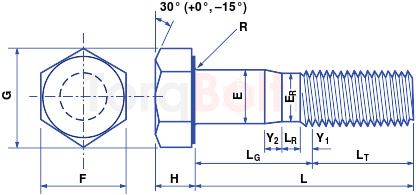
ASTM F3111 Heavy Hex Bolts
| Parameters | Range | Size | ||
|---|---|---|---|---|
| Nominal Size | ... | 1 | 1 1/8 | 1 1/4 |
| Basic Diameter, E, in. | ... | 1.000 | 1.125 | 1.250 |
| Full-Size Body Diameter E, in. | max | 1.022 | 1.149 | 1.277 |
| min | 0.976 | 1.098 | 1.223 | |
| Width Across Flats, F, in.A | nom | 1 5/8 | 1 13/16 | 2 |
| max | 1.625 | 1.812 | 2.000 | |
| min | 1.575 | 1.756 | 1.938 | |
| Width Across Corners, G, in. | max | 1.876 | 2.093 | 2.309 |
| min | 1.796 | 2.002 | 2.209 | |
| Head Height, H, in.B | nom | 39/64 | 11/16 | 25/32 |
| max | 0.627 | 0.718 | 0.813 | |
| min | 0.591 | 0.658 | 0.749 | |
| Radius of Fillet, R, in. | nom | 3/32 | 3/32 | 7/64 |
| max | 0.110 | 0.110 | 0.138 | |
| min | 0.087 | 0.087 | 0.098 | |
| Transition Body Diameter, ER, in. | nom | 59/64 | 1 1/32 | 1 5/32 |
| max | 0.933 | 1.046 | 1.171 | |
| min | 0.917 | 1.030 | 1.155 | |
| Body Transition Length, Y2, in. | nom | 0.305 | 0.354 | 0.354 |
| max | 0.394 | 0.450 | 0.450 | |
| min | 0.207 | 0.244 | 0.244 | |
| Reduced Body Length, LR, in. | nom | 1/2 | 9/16 | 9/16 |
| max | 0.625 | 0.715 | 0.715 | |
| min | 0.375 | 0.429 | 0.429 | |
| Transition Thread Length Y1, in.C | Ref | 0.31 | 0.34 | 0.34 |
| Thread Length, LT, in.D | Ref | 2.049 | 2.322 | 2.322 |
| Maximum Total Runout of Bearing Surface FIM, in.E | . . . | 0.028 | 0.032 | 0.035 |
|
||||
ASTM F3111 Heavy Hex Nut Dimensions

| Parameters | Range | Size | ||
|---|---|---|---|---|
| Nominal Size | . . . | 1 | 1 1/8 | 1 1/4 |
| . . . | 1.000 | 1.125 | 1.250 | |
| Width Across Flats, F, in.A | nom | 1 5/8 | 1 13/16 | 2 |
| max | 1.625 | 1.812 | 2.000 | |
| min | 1.575 | 1.756 | 1.938 | |
| Width Across Corners, G, in.B | max | 1.876 | 2.093 | 2.309 |
| min | 1.796 | 2.002 | 2.209 | |
| Thickness, H, in.C | nom | 1 3/16 | 1 11/32 | 1 15/32 |
| max | 1.214 | 1.367 | 1.501 | |
| min | 1.147 | 1.295 | 1.424 | |
| Washer Face Height, in. | nom | 1/64 | 1/64 | 1/64 |
| Total Runout of Bearing Face FIM, in.D | . . . | 0.024 | 0.027 | 0.030 |
|
||||
ASTM F3111 Hardened Circular Washers Dimensions

| Paarameters | Range | Size | ||
|---|---|---|---|---|
| Nominal Size | . . . | 1 | 1 1/8 | 1 1/4 |
| Inside Diameter (ID), in. | nom | 1 1/16 | 1 3/16 | 1 3/8 |
| max | 1.085 | 1.251 | 1.438 | |
| min | 1.063 | 1.188 | 1.375 | |
| Outside Diameter (OD), in. | nom | 2 | 2 1/4 | 2 1/2 |
| max | 2.063 | 2.313 | 2.563 | |
| min | 1.937 | 2.187 | 2.437 | |
| Thickness (T), in. | nom | 1/4 | 1/4 | 5/16 |
| max | 0.264 | 0.264 | 0.343 | |
| min | 0.209 | 0.209 | 0.287 | |
ASTM F3111 Basic Thread Dimensions, Grade 2 Assemblies

| Paarameters | Size | ||
|---|---|---|---|
| Nominal Size, in. | 1 | 1 1/8 | 1 1/4 |
| Major Diameter, in. | 0.9980 | 1.1228 | 1.2478 |
| Threads per inch | 8 | 7 | 7 |
| Pitch, in. | 0.1250 | 0.1429 | 0.1429 |
| A, in. | 0.0135 | 0.0155 | 0.0155 |
| B, in. | 0.0460 | 0.0526 | 0.0526 |
| C, in. | 0.0106 | 0.0121 | 0.0121 |
| D, in. | 0.0381 | 0.0435 | 0.0435 |
| E, in. | 0.0167 | 0.0190 | 0.0190 |
| F, in. | 0.0281 | 0.0321 | 0.0321 |
| G, in. | 0.0180 | 0.0206 | 0.0206 |
| H, in. | 0.1083 | 0.1237 | 0.1237 |
| J, in. | 0.0722 | 0.0825 | 0.0825 |
| M, in. | 0.0054 | 0.0062 | 0.0062 |
| Q, in. | 0.1104 | 0.1261 | 0.1261 |
|
|||
ASTM F3111 Bolting Surface Treatment Specifications
ASTM F3111 Bolting Components Marking
Product Shall be Marked with our manufacturing trade mark "TorqBolt" or "TB" along with the
designated Grade.
Grade and manufacturer’s identification symbols shall be applied to one end of studs and to the heads of bolts
and screws of all sizes. (If the available area is inadequate, the grade symbol may be marked on one end and
the manufacturer’s identification symbol marked on the other end.) For bolts and screws smaller than 1⁄4 in.
[6 mm] in diameter and studs smaller than 3⁄8 in. [10 mm] in diameter and for 1⁄4 in. [6 mm] in diameter studs
requiring more than a total of three symbols, the marking shall be a matter of agreement between the purchaser
and the manufacturer.
ASME Dimensional Standards
B18.2.6M -
Heavy Hex Structural Bolts (Metric Series)
B18.2.2 - Heavy Hex Nuts Washer
faced
ASTM F3111 Bolting Certifications
- EN 10204 3.1
- EN 10204 3.2
- PED 2014/68/EC
- MERKBLATT AD 2000 W2/W7/W10
- API 20 E BSL 1/ BSL 2
- NACE MR 0175
- NACE MR 0103
ASTM F3111 Testing Standards
A751 Test Methods, Practices, and Terminology for Chemical Analysis of Steel
Products
E23 Test Methods for Notched Bar Impact Testing of Metallic Materials
E709 Guide for Magnetic Particle Testing
E1268 Practice for Assessing the Degree of Banding or Orientation of Microstructures
E1417/E1417M Practice for Liquid Penetrant Testing
E1444/E1444M Practice for Magnetic Particle Testing
E2884 Guide for Eddy Current Testing of Electrically Conducting Materials Using
Conformable Sensor Arrays
F606/F606M Test Methods for Determining the Mechanical Properties of Externally and
Internally Threaded Fasteners, Washers, Direct Tension Indicators, and Rivets
F788/F788M Specification for Surface Discontinuities of Bolts, Screws, and Studs, Inch and
Metric Series
F1470 Practice for Fastener Sampling for Specified Mechanical Properties and Performance
Inspection
F2328 Test Method for Determining Decarburization and Carburization in Hardened and
Tempered, Threaded, Steel Bolts, Screws, Studs, and Nuts