ASTM F3043 tension Control Bolt Specification
Quenched & Tempered Alloy Steel Twist Off Type Tension Control Bolts Nuts & Washers
ASTM F3043 Tension Control TC Bolts
ASTM F3043 pecification covers one style of heat treated,
alloy steel, tension control bolt-nut-washer assemblies, also referred to as "sets," having a
tensile strength of 200 to 215 ksi. These assemblies are capable of developing a minimum
predetermined tension when installed by applying torque to the nut, while at the same time applying
a counter torque to separate the spline end from the body of the bolt using an appropriate spline
drive installation tool. An assembly consists of a tension control bolt with spline end, nut and
washer covered by this specification. The assemblies are available with round heads in sizes 1 inch
to 1 1/4 inch inclusive. The fastener assemblies are intended for use in structural connections in
the following environmental conditions:
Interiors, normally dry, including interiors where
structural steel is embedded in concrete, encased in masonry or protected by membrane or
noncorrosive contact type fireproofing.
Interiors and exteriors, normally dry, under roof, where
the installed assemblies are soundly protected by a shop-applied or field-applied coating to the
structural steel system.
ASTM F3043 Chemical Requirements
ASTM F3043 Chemical Requirements for Tension Control BoltsA
| Element | Heat Analysis, % | Product Analysis, % | ||
|---|---|---|---|---|
| min | max | min | max | |
| C | 0.38 | 0.42 | 0.36 | 0.44 |
| Mn | 0.40 | 0.60 | 0.37 | 0.63 |
| P | . . . | 0.01 | . . . | 0.015 |
| S | . . . | 0.01 | . . . | 0.015 |
| Si | . . . | 0.10 | . . . | 0.12 |
| Cr | 1.20 | 1.40 | 1.15 | 1.45 |
| Mo | 0.60 | 0.80 | 0.57 | 0.83 |
| V | 0.30 | 0.40 | 0.27 | 0.43 |
|
||||
ASTM F3043 Chemical Requirements for Nuts
| Element | Heat Analysis, % | Product Analysis, % | ||
|---|---|---|---|---|
| min | max | min | max | |
| C | 0.30 | 0.48 | 0.28 | 0.50 |
| Mn | 0.60 | 0.90 | 0.57 | 0.93 |
| Si | 0.15 | 0.35 | 0.13 | 0.37 |
| P | . . . | 0.050 | . . . | 0.055 |
| S | . . . | 0.050 | . . . | 0.055 |
ASTM F3043 Chemical Requirements for Washers
| Element | Heat Analysis, % | Product Analysis, % | ||
|---|---|---|---|---|
| min | max | min | max | |
| C | 0.42 | 0.48 | 0.40 | 0.50 |
| Mn | 0.60 | 0.90 | 0.57 | 0.93 |
| Si | 0.15 | 0.35 | 0.13 | 0.37 |
| P | . . . | 0.030 | . . . | 0.035 |
| S | . . . | 0.030 | . . . | 0.035 |
ASTM F3043 Mechanical Requirements
ASTM F3043 Hardness Requirements for Tension Control Bolts
| Bolt Size, in. | Bolt Length, in. | Rockwell C | |
|---|---|---|---|
| min | max | ||
| 1 to 11/4 , incl | all | 38 | 45 |
ASTM F3043 Tensile Requirements for Full Size Tension Control Bolts
| Grade | Bolt Size, Threads per in. | Stress Area, in.2 A,B | Tensile Load, lbfC | |
|---|---|---|---|---|
| min | max | |||
| ASTM A3043 Grade 1 | 1 in. - 8 | 0.615 | 123 100 | 132 300 |
| 11/8 in. - 7 | 0.776 | 155 200 | 166 800 | |
| 11/4 in. - 7 | 0.983 | 196 700 | 211 400 | |
| ASTM A3043 Grade 2 | 1 in. - 8 | 0.640 | 128 000 | 137 700 |
| 11/8 in. - 7 | 0.808 | 161 600 | 173 600 | |
| 11/4 in. - 7 | 1.019 | 203 800 | 219 100 | |
|
||||
ASTM F3043 Tensile Strength Requirements for Specimens Machined from Bolts
| Nominal Diameter, in. | Tensile Strength, ksi | Yield Strength (0.2 % offset), min, ksi | Elongation in 2 in. or 50 mm, min, % | Reduction of Area, min, % | |
|---|---|---|---|---|---|
| min | max | ||||
| 1 to 11/4 , incl | 200 | 215 | 180 | 14 | 40 |
ASTM F3043 Hardness Requirements for Nuts
| Bolt Size, in. | Surface Hardness, Rockwell C | |
|---|---|---|
| min | max | |
| 1 to 11/4 , incl | 30 | 40 |
ASTM F3043 Proof Load Requirements for Nuts
| Grade | Nominal Size - Threads per in. | Stress Area, As, in.2 A,B | Proof Load Stress, ksi | Nut Proof Load, lbfC |
|---|---|---|---|---|
| ASTM A3043 Grade 1 | 1 in. - 8 | 0.615 | 200 | 123 100 |
| 11/8 in. - 7 | 0.776 | 200 | 155 200 | |
| 11/4 in. - 7 | 0.983 | 200 | 196 700 | |
| ASTM A3043 Grade 2 | 1 in. - 8 | 0.640 | 200 | 128 000 |
| 11/8 in. - 7 | 0.808 | 200 | 161 600 | |
| 11/4 in. - 7 | 1.019 | 200 | 203 800 | |
|
||||
ASTM F3043 Core Hardness Requirements for Washers
| Rockwell C | |
|---|---|
| Min 40 | Max 45 |
ASTM F3043 Assembly Lot Tension Test Requirements
| Bolt Size, in. | Grade 1 | Grade 2 | ||
|---|---|---|---|---|
| Manufacturers Acceptance Test Tension, lbs, minA | Tension lbs, min (for information only)B | Manufacturers Acceptance Test Tension, lbs, minA | Tension lbs, min (for information only)B | |
| 1 | 90 000 | 86 000 | 94 000 | 90 000 |
| 11/8 | 114 000 | 109 000 | 119 000 | 113 000 |
| 11/4 | 145 000 | 138 000 | 150 000 | 143 000 |
|
||||
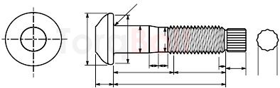
ASTM F3043 Tension Control Bolt Dimensions
| Parameters | Range | Size | ||
|---|---|---|---|---|
| Nominal Size | ... | 1 | 11/8 | 11/4 |
| Basic Diameter, E, in.A | ... | 1.000 | 1.125 | 1.250 |
| Full-Size Body Diameter E, in. | max | 1.022 | 1.149 | 1.277 |
| min | 0.976 | 1.098 | 1.223 | |
| Head Height, H, in.B | nom | 39/64 | 11/16 | 25/32 |
| max | 0.643 | 0.738 | 0.824 | |
| min | 0.607 | 0.678 | 0.759 | |
| Head Diameter, D, in.C | nom | 21/8 | 23/8 | 21/2 |
| max | 2.158 | 2.375 | 2.589 | |
| Bearing Diameter, C, in.D | nom | 2 | 21/4 | 21/2 |
| min | 1.771 | 1.991 | 2.224 | |
| Radius of Fillet, R, in. | nom | 3/32 | 3/32 | 7/64 |
| max | 0.110 | 0.110 | 0.138 | |
| min | 0.087 | 0.087 | 0.098 | |
| Transition Body Diameter, ER, in. | nom | 59/64 | 11/32 | 15/32 |
| max | 0.933 | 1.046 | 1.171 | |
| min | 0.917 | 1.030 | 1.155 | |
| Body Transition Length, Y2, in. | nom | 0.305 | 0.354 | 0.354 |
| max | 0.394 | 0.450 | 0.450 | |
| min | 0.207 | 0.244 | 0.244 | |
| Reduced Body Length, LR, in. | nom | 1/2 | 9/16 | 9/16 |
| max | 0.625 | 0.715 | 0.715 | |
| min | 0.375 | 0.429 | 0.429 | |
| Transition Thread Length Y1, in.E | Ref | 0.31 | 0.34 | 0.34 |
| Thread Length, LT, in.F | Ref | 2.049 | 2.322 | 2.322 |
| Maximum center of groove to First Fully Formed Thread, U, in.G | Max | 0.455 | 0.500 | 0.500 |
| Spline Length, Ls, in.H | Ref | 0.80 | 0.90 | 0.984 |
| Spline Width Across Flats, S, in.H | Ref | 0.700 | 0.787 | 0.897 |
|
||||
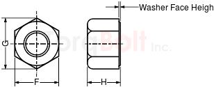
ASTM F3043 Nut Dimensions
| Parameters | Range | Size | ||
|---|---|---|---|---|
| Nominal SizeA | . . . | 1 | 11/8 | 11/4 |
| . . . | 1.000 | 1.125 | 1.250 | |
| Width Across Flats, FB | nom | 15/8 | 113/16 | 2 |
| max | 1.625 | 1.812 | 2.000 | |
| min | 1.575 | 1.756 | 1.938 | |
| Width Across Corners, GC | max | 1.876 | 2.093 | 2.309 |
| min | 1.796 | 2.002 | 2.209 | |
| Thickness, HD | nom | 13/16 | 111/32 | 115/32 |
| max | 1.214 | 1.367 | 1.501 | |
| min | 1.147 | 1.295 | 1.424 | |
| Washer Face Height | nom | 1/64 | 1/64 | 1/64 |
| Total Runout of Bearing Face FIME | 0.024 | 0.027 | 0.030 | |
|
||||
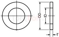
ASTM F3043 Hardened Circular Washers Dimensions
| Parameters | Range | Size | ||
|---|---|---|---|---|
| Nominal Size | . . . | 1 | 11/8 | 11/4 |
| Inside Diameter (ID), in. | nom | 11/16 | 13/16 | 13/8 |
| max | 1.085 | 1.251 | 1.438 | |
| min | 1.063 | 1.188 | 1.375 | |
| Outside Diameter (OD), in. | nom | 2 | 21/4 | 21/2 |
| max | 2.063 | 2.313 | 2.563 | |
| min | 1.937 | 2.187 | 2.437 | |
| Thickness (T), in. | nom | 1/4 | 1/4 | 5/16 |
| max | 0.264 | 0.264 | 0.343 | |
| min | 0.209 | 0.209 | 0.287 | |
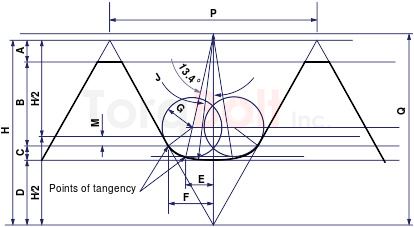
ASTM F3043 Basic Thread Dimensions, Grade 2 Assemblies
| Parameters | Size | ||
|---|---|---|---|
| Nominal Size, in. | 1 | 11/8 | 11/4 |
| Major Diameter, in. | 0.9980 | 1.1228 | 1.2478 |
| Threads per inch | 8 | 7 | 7 |
| Pitch, in. | 0.1250 | 0.1429 | 0.1429 |
| A, in. | 0.0135 | 0.0155 | 0.0155 |
| B, in. | 0.0460 | 0.0526 | 0.0526 |
| C, in. | 0.0106 | 0.0121 | 0.0121 |
| D, in. | 0.0381 | 0.0435 | 0.0435 |
| E, in. | 0.0167 | 0.0190 | 0.0190 |
| F, in. | 0.0281 | 0.0321 | 0.0321 |
| G, in. | 0.0180 | 0.0206 | 0.0206 |
| H, in. | 0.1083 | 0.1237 | 0.1237 |
| J, in. | 0.0722 | 0.0825 | 0.0825 |
| M, in. | 0.0054 | 0.0062 | 0.0062 |
| Q, in. | 0.1104 | 0.1261 | 0.1261 |
|
|||
ASTM F3043 Pre-Installation Verification Testing, Pretensioning And Inspection
| Bolt Size, in. | Pretension, pounds, min | |
|---|---|---|
| Grade 1 | Grade 2 | |
| 1 | 90 000 | 94 000 |
| 11/8 | 114 000 | 119 000 |
| 11/4 | 145 000 | 150 000 |
ASTM F3043 Bolting Surface Treatment Specifications
ASTM F3043 Bolting Components Marking
Product Shall be Marked with our manufacturing trade mark "TorqBolt" or "TB" along with
the designated Grade.
Grade and manufacturer’s identification symbols shall be applied to one end of studs and to the
heads of bolts and screws of all sizes. (If the available area is inadequate, the grade symbol may
be marked on one end and the manufacturer’s identification symbol marked on the other end.) For
bolts and screws smaller than 1⁄4 in. [6 mm] in diameter and studs smaller than 3⁄8 in. [10 mm] in
diameter and for 1⁄4 in. [6 mm] in diameter studs requiring more than a total of three symbols, the
marking shall be a matter of agreement between the purchaser and the manufacturer.
ASME Dimensional Standards
B18.2.6
Tension control bolts with Round Head
B18.2.6M -
Heavy Hex Structural Bolts (Metric Series)
ASTM F3043 Bolting Certifications
- EN 10204 3.1
- EN 10204 3.2
- PED 2014/68/EC
- MERKBLATT AD 2000 W2/W7/W10
- API 20 E BSL 1/ BSL 2
- NACE MR 0175
- NACE MR 0103
ASTM F3043 Testing Standards
A751 Test Methods, Practices, and Terminology for Chemical Analysis of Steel
Products
E709 Guide for Magnetic Particle Testing
F606/F606M Test Methods for Determining the Mechanical Properties of
Externally and Internally Threaded Fasteners, Washers, Direct Tension Indicators, and Rivets
F788/F788M Specification for Surface Discontinuities of Bolts, Screws, and
Studs, Inch and Metric Series
E1444/E1444M Practice for Magnetic Particle Testing
F1470 Practice for Fastener Sampling for Specified Mechanical Properties
and Performance Inspection
F2328 Test Method for Determining Decarburization and Carburization in
Hardened and Tempered, Threaded, Steel Bolts, Screws, Studs, and Nuts