DIN 580 Specification
Lifting Eye Bolts
DIN 580 Scope
DIN 580 Specification specifies the properties of steel and stainless steel eyebolts and provides information on their correct use in lifting operations (as part of slings and as load handling equipment).
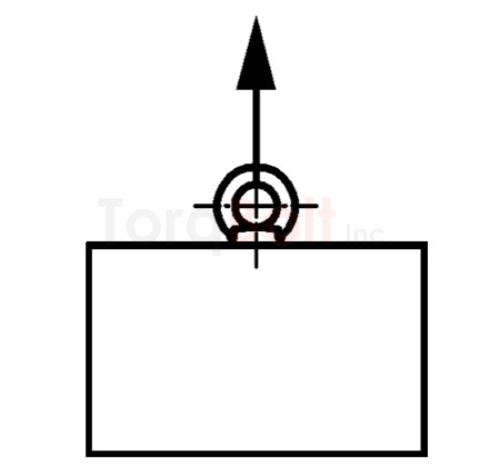
Eye bolts according to this standard can be used in a temperature range from −20 ° C to +200 ° C without any restriction of the load capacity.
DIN 580 Dimensions

-
Key :
- 1 conical tip (CH) or lens tip (RN) according to DIN EN ISO 4753 at the manufacturer's choice.
- NOTE : Center bores in the upper ring area are permissible for Sizes above M36
| Thread, d1 |
d2 | d3 | d4 | e | f | dg | h | k | l js15 | Weight kg / piece ≈ |
|||||||||||||||
|---|---|---|---|---|---|---|---|---|---|---|---|---|---|---|---|---|---|---|---|---|---|---|---|---|---|
| Size | min. | max. | Size | min. | max. | Size | min. | max. | Size | min. | max. | max. | Size= max |
min. | Size | min. | max. | Size | min. | max. | Size | min. | max. | ||
| DIN 580 M6 | 20 | 19.5 | 20.9 | 36 | 35.5 | 37.1 | 20 | 19.1 | 20.5 | 6 | 5.5 | 6.9 | 2.5 | 4.4 | 4.22 | 36 | 35.5 | 37.1 | 8 | 7.5 | 8.9 | 13 | 12.65 | 13.35 | 0.0572 |
| DIN 580 M8 | 20 | 19.5 | 20.9 | 36 | 35.5 | 37.1 | 20 | 19.1 | 20.5 | 6 | 5.5 | 6.9 | 2.5 | 6 | 5.82 | 36 | 35.5 | 37.1 | 8 | 7.5 | 8.9 | 13 | 12.65 | 13.35 | 0.06 |
| DIN 580 M10 | 25 | 24.5 | 25.9 | 45 | 44.5 | 46.1 | 25 | 24.1 | 25.5 | 8 | 7.5 | 8.9 | 3 | 7.7 | 7.48 | 45 | 44.5 | 46.1 | 10 | 9.5 | 10.9 | 17 | 16.65 | 17.35 | 0.11 |
| DIN 580 M12 | 30 | 29.5 | 30.9 | 54 | 53.5 | 55.1 | 30 | 29.1 | 30.5 | 10 | 9.5 | 10.9 | 3.5 | 9.4 | 9.18 | 53 | 52.5 | 54.1 | 12 | 11.5 | 12.9 | 20.5 | 20.08 | 20.92 | 0.18 |
| DIN 580 M14 | 35 | 34.5 | 36.1 | 63 | 62.5 | 64.1 | 35 | 33.9 | 35.5 | 12 | 11.5 | 12.9 | 4 | 11 | 10.73 | 62 | 61.5 | 63.1 | 14 | 13.5 | 14.9 | 27 | 26.58 | 27.42 | 0.27 |
| DIN 580 M16 | 35 | 34.5 | 36.1 | 63 | 62.5 | 64.1 | 35 | 33.9 | 35.5 | 12 | 11.5 | 12.9 | 4 | 13 | 12.73 | 62 | 61.5 | 63.1 | 14 | 13.5 | 14.9 | 27 | 26.58 | 27.42 | 0.28 |
| DIN 580 M18 | 40 | 39.5 | 41.1 | 72 | 71.5 | 73.1 | 40 | 38.9 | 40.5 | 14 | 13.5 | 14.9 | 5 | 14.4 | 14.13 | 71 | 70.5 | 72.1 | 16 | 15.5 | 16.9 | 30 | 29.58 | 30.42 | 438 |
| DIN 580 M20 | 40 | 39.5 | 41.1 | 72 | 71.5 | 73.1 | 40 | 38.9 | 40.5 | 14 | 13.5 | 14.9 | 5 | 16.4 | 16.13 | 71 | 70.5 | 72.1 | 16 | 15.5 | 16.9 | 30 | 29.58 | 30.42 | 0.45 |
| DIN 580 M22 | 50 | 49.4 | 51.2 | 90 | 89.4 | 91.2 | 50 | 48.8 | 50.6 | 18 | 17.5 | 19.1 | 6 | 18.4 | 18.07 | 90 | 89.4 | 91.2 | 20 | 19.5 | 21.1 | 36 | 35.5 | 36.5 | 725 |
| DIN 580 M24 | 50 | 49.4 | 51.2 | 90 | 89.4 | 91.2 | 50 | 48.8 | 50.6 | 18 | 17.5 | 19.1 | 6 | 19.6 | 19.27 | 90 | 89.4 | 91.2 | 20 | 19.5 | 21.1 | 36 | 35.5 | 36.5 | 0.74 |
| DIN 580 M27 | 65 | 64.3 | 66.3 | 108 | 107.3 | 109.5 | 60 | 58.7 | 60.7 | 22 | 21.4 | 23.2 | 7 | 22.6 | 22.29 | 109 | 108.3 | 110.5 | 24 | 23.4 | 25.2 | 45 | 44.5 | 45.5 | 1624 |
| DIN 580 M30 | 65 | 64.3 | 66.3 | 108 | 107.3 | 109.5 | 60 | 58.7 | 60.7 | 22 | 21.4 | 23.2 | 7 | 25 | 24.67 | 109 | 108.3 | 110.5 | 24 | 23.4 | 25.2 | 45 | 44.5 | 45.5 | 1.66 |
| DIN 580 M33 | 75 | 74.3 | 76.5 | 126 | 125.2 | 127.7 | 70 | 68.5 | 70.7 | 26 | 25.3 | 27.3 | 8 | 28 | 27.61 | 128 | 127.2 | 129.7 | 28 | 27.3 | 29.3 | 54 | 53.5 | 54.5 | 2596 |
| DIN 580 M36 | 75 | 74.3 | 76.5 | 126 | 125.2 | 127.7 | 70 | 68.5 | 70.7 | 26 | 25.3 | 27.3 | 8 | 30.3 | 29.91 | 128 | 127.2 | 129.7 | 28 | 27.3 | 29.3 | 54 | 53.5 | 54.5 | 2.65 |
| DIN 580 M39 | 85 | 84.3 | 86.5 | 144 | 143.2 | 145.7 | 80 | 78.5 | 80.7 | 30 | 29.3 | 31.3 | 9 | 33.3 | 32.91 | 147 | 146.2 | 148.7 | 32 | 31.3 | 33.3 | 63 | 62.4 | 63.6 | 3.78 |
| DIN 580 M42 | 85 | 84.3 | 86.5 | 144 | 143.2 | 145.7 | 80 | 78.5 | 80.7 | 30 | 29.3 | 31.3 | 9 | 35.6 | 35.21 | 147 | 146.2 | 148.7 | 32 | 31.3 | 33.3 | 63 | 62.4 | 63.6 | 4.03 |
| DIN 580 M45 | 100 | 99.2 | 101.7 | 166 | 164.9 | 168.1 | 90 | 88.3 | 90.8 | 35 | 34.2 | 36.7 | 10 | 38.6 | 38.21 | 168 | 166.9 | 170.1 | 38 | 37.2 | 39.7 | 68 | 67.4 | 68.6 | 6244 |
| DIN 580 M48 | 100 | 99.2 | 101.7 | 166 | 164.9 | 168.1 | 90 | 88.3 | 90.8 | 35 | 34.2 | 36.7 | 10 | 41 | 40.61 | 168 | 166.9 | 170.1 | 38 | 37.2 | 39.7 | 68 | 67.4 | 68.6 | 6.38 |
| DIN 580 M52 | 110 | 108.9 | 112.1 | 184 | 182.8 | 186.4 | 100 | 98.1 | 100.9 | 38 | 37.1 | 39.9 | 11 | 45 | 44.54 | 187 | 185.8 | 189.4 | 42 | 41.1 | 43.9 | 78 | 77.4 | 78.6 | 8566 |
| DIN 580 M56 | 110 | 108.9 | 112.1 | 184 | 182.8 | 186.4 | 100 | 98.1 | 100.9 | 38 | 37.1 | 39.9 | 11 | 48.3 | 47.91 | 187 | 185.8 | 189.4 | 42 | 41.1 | 43.9 | 78 | 77.4 | 78.6 | 8.8 |
| DIN 580 M60 | 120 | 118.9 | 122.1 | 206 | 204.8 | 208.4 | 110 | 107.9 | 111.1 | 42 | 41.1 | 43.9 | 12 | 52.3 | 51.84 | 208 | 206.8 | 210.4 | 48 | 47.1 | 49.9 | 90 | 89.3 | 90.7 | 12.13 |
| DIN 580 M64 | 120 | 118.9 | 122.1 | 206 | 204.8 | 208.4 | 110 | 107.9 | 111.1 | 42 | 41.1 | 43.9 | 12 | 55.7 | 55.24 | 208 | 206.8 | 210.4 | 48 | 47.1 | 49.9 | 90 | 89.3 | 90.7 | 12.4 |
| DIN 580 M72 × 6 |
150 | 148.8 | 152.4 | 260 | 258.5 | 263 | 140 | 137.6 | 141.2 | 50 | 48.9 | 52.1 | 12 | 63.7 | 63.24 | 260 | 258.5 | 263 | 60 | 58.9 | 62.1 | 100 | 99.3 | 100.7 | 23.3 |
| DIN 580 M80 × 6 |
170 | 168.5 | 173 | 296 | 294.3 | 299.3 | 160 | 157.3 | 161.3 | 55 | 53.8 | 57.4 | 12 | 71.7 | 71.24 | 298 | 296.3 | 301.3 | 68 | 66.8 | 70.4 | 112 | 111.3 | 112.7 | 34.2 |
| DIN 580 M100 × 6 |
190 | 188.5 | 193 | 330 | 328.3 | 333.3 | 180 | 177 | 181.5 | 60 | 58.8 | 62.4 | 12 | 91.7 | 91.16 | 330 | 328.3 | 333.3 | 75 | 73.8 | 77.4 | 130 | 129.2 | 130.8 | 49.1 |
DIN 580 Minimum Breaking Forces
| Thread, d1 | Minimum breaking force in axial pull |
Minimum breaking force in transverse tension 90 ° |
|---|---|---|
| M6 | 4.4 | 2.2 |
| M8 | 8.2 | 4.1 |
| M10 | 13.5 | 6.8 |
| M12 | 20 | 10 |
| M14 | 28.8 | 14.4 |
| M16 | 41.2 | 20.6 |
| M18 | 50 | 25 |
| M20 | 70.6 | 35.3 |
| M22 | 82.4 | 41.2 |
| M24 | 106 | 53 |
| M27 | 124 | 61.8 |
| M30 | 189 | 94.2 |
| M33 | 189 | 94.2 |
| Thread, d1 | Minimum breaking force in axial pull |
Minimum breaking force in transverse tension 90 ° |
|---|---|---|
| M36 | 271 | 136 |
| M39 | 271 | 136 |
| M42 | 371 | 186 |
| M45 | 371 | 186 |
| M48 | 507 | 254 |
| M52 | 507 | 259 |
| M56 | 677 | 339 |
| M60 | 677 | 339 |
| M64 | 942 | 471 |
| M72 × 6 | 1177 | 589 |
| M80 × 6 | 1648 | 824 |
| M100 × 6 | 2354 | 1177 |
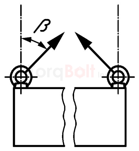
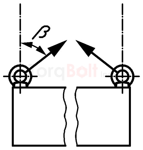
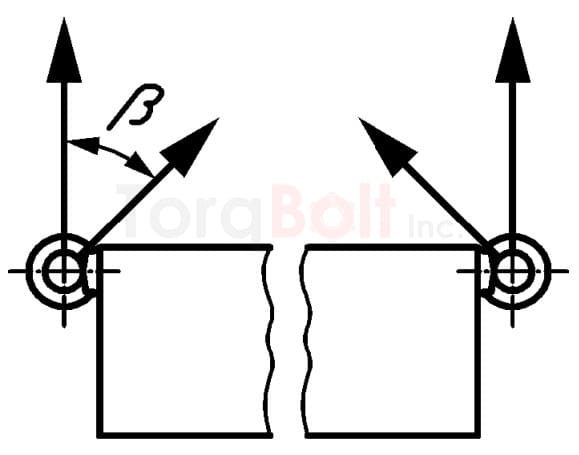
DIN 580 Load capacity
| Thread , d1 | Axial load capacity (WLL) per eye bolt |
Load capacity per eye bolt 0 ° <β ≤ 45 ° |
Load capacity per eye bolt β> 45 ° to 60 ° |
Load capacity screwed in from the side per eye bolt 0 ° ≤ β ≤ 45 ° |
|---|---|---|---|---|
 |
 |
 |
 |
|
| M6 | 75 | 55 | 38 | |
| M8 | 140 | 100 | 70 | |
| M10 | 230 | 170 | 115 | |
| M12 | 340 | 240 | 170 | |
| M14 | 490 | 350 | 445 | |
| M16 | 700 | 500 | 350 | |
| M18 | 850 | 600 | 425 | |
| M20 | 1200 | 860 | 600 | |
| M22 | 1400 | 1000 | 700 | |
| M24 | 1800 | 1290 | 900 | |
| M27 | 2100 | 1500 | 1050 | |
| M30 | 3200 | 2300 | 1600 | |
| M33 | 3200 | 2300 | 1600 | |
| M36 | 4600 | 3300 | 2300 | |
| M39 | 4600 | 3300 | 2300 | |
| M42 | 6300 | 4500 | 3150 | |
| M45 | 6300 | 4500 | 3150 | |
| M48 | 8600 | 6100 | 4300 | |
| M52 | 8600 | 6100 | 4300 | |
| M56 | 11500 | 8200 | 5750 | |
| M60 | 11500 | 8200 | 5750 | |
| M64 | 16000 | 11000 | 8000 | |
| M72×6 | 20000 | 14000 | 10000 | |
| M80×6 | 28000 | 20000 | 14000 | |
| M100×6 | 40000 | 29000 | 20000 | |
DIN 580 Technical Delivery Conditions
| Material | Steel | Stainless steel | |
|---|---|---|---|
| General Requirements | Standard | DIN EN 10254 | |
| Execution | Normal annealed, fine grain with structure ratio fine 5 |
solution annealed | |
| Standards | DIN EN ISO 643 | DIN EN 10263-5 | |
| Ring screws must be cleanly forged in the die. The dimensional tolerances according to DIN EN 10243-1 apply to the dimensions of the unprocessed part as well as to the burr and die replacement. |
|||
| Thread | Tolerance | 6g / screw-in group N 6az for hot-dip galvanizing | |
| Standards | DIN ISO 965-1, DIN ISO 965-4 | ||
| Materials | C15E with an aluminium content of 0.025% to 0.050% | A2, A3, A4, A5 | |
| Standards | DIN EN 10084 | chemical composition according to DIN EN ISO 3506-1 | |
| Minimum breaking forces | See Table 2. | ||
| Surface finish - Coating | as manufactured DIN EN ISO 4042 applies to galvanic surface protection. DIN EN ISO 10684 applies to hot-dip galvanizing. |
passivated according to DIN EN ISO 16048 | |
| Surface defects | DIN EN 26157-3 applies to limit values for surface defects. | - | |
| Acceptance check | DIN EN ISO 3269 | ||